Len Long’s Projects – Build a Surveillance Recorder

On the behalf of my good friend, I am posting a number of his project write-ups for the electronics hobbyist community. In what I hope will the first of many more, learn how to:

BUILD A VIDEO SURVEILLANCE STORAGE RECORDER

Len Long, W1ZTL


INTRODUCTION

This article describes how to build and configure a simple video acquisition system which includes inexpensive wifi cameras, a tiny Windows based computer, a fan, required interfaces and power modules.

PURPOSE

The purpose of this article is to provide the reader with detailed information on an easy to build video surveillance storage recorder.

SCOPE

The scope of this article is aimed at people who enjoy building, have a need for a video surveillance system, and who know how to operate a Windows 10 computer.

SYSTEM DESCRIPTION

This system utilizes an Intel Stick computer which was designed to bring Internet and other inputs to a television set with an HDMI input. Free ContaCam software allows one to provide all of the functions of a professionally marketed system. Assembly is easy. You take the Intel Stick and plug in the USB to Ethernet adapter into one of the Stick’s USB ports and plug in the LAN into your switch or router. An option would be to use the WiFi capability of the stick but I chose to plug it in because of the limited range of the Stick. At the fan’s input you want to protect the Stick from spikes so place series diodes and a 1 microfarad and 10 microfarad capacitor in parallel with the series diodes in the circuit. Load the Stick with TightVNC as well as your LAN connected computer and you have a remote desktop that you can use for adjusting the software, viewing the output of your cameras, and playing back any part of the video that is stored. Plug in the 5 volt wall wart and you are in business.

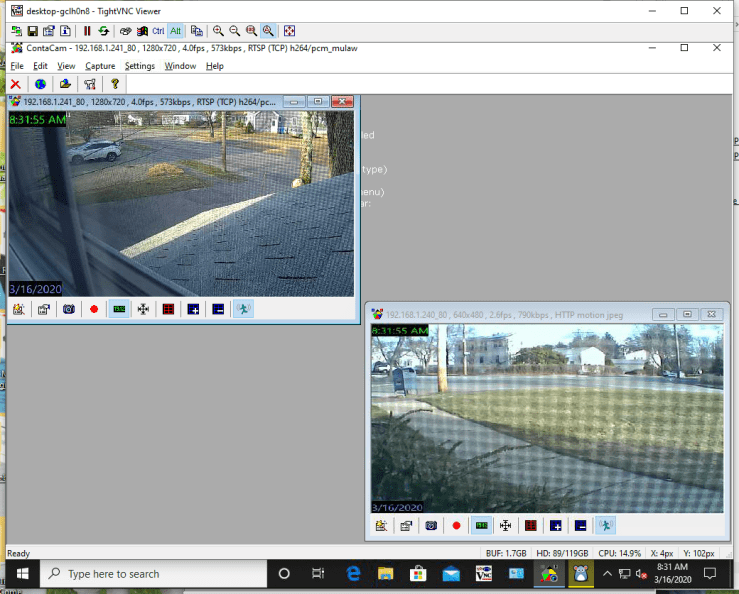
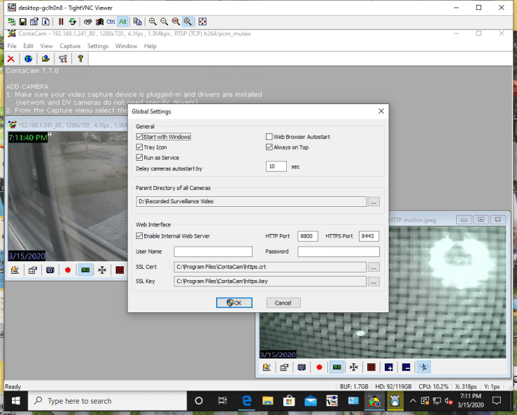
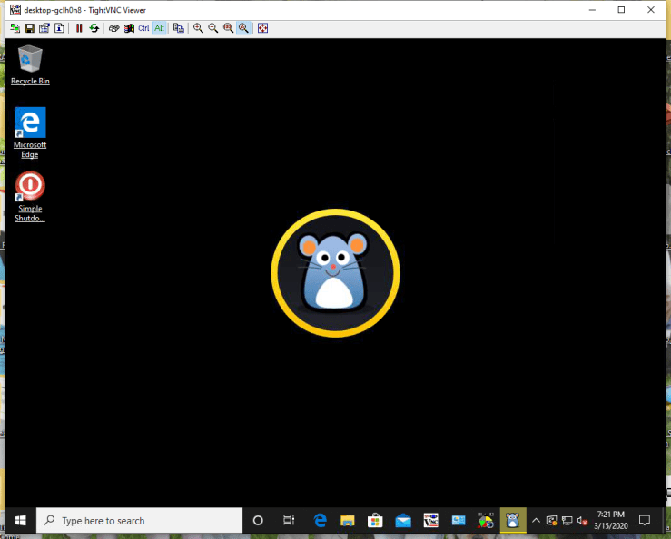
The following figure is what you see on your remote, LAN connected computer

1

Initial setting up the Intel Stick includes plugging on the HDMI input of a display and placing a mouse into one of the USB ports. Download and excute TightVNC and the rest can be done remotely.

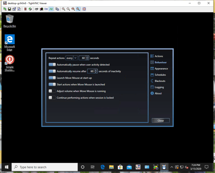
Load ContaCam and Move Mouse software and adjust MoveMouse to synthesize mouse movements every minute. Then setup the ContCam software as in the figures.

HARDWARE

The system goes together very easily and quickly. You can plug in a USB camera or several with a powered hub or use inexpensive Foscam WiFi cameras. With a USB camera plugged into my system, the system failed periodically so I just use the Wi-Fi cameras.

https://smile.amazon.com/gp/product/B006DAOJTY/ref=ppx_yo_dt_b_search_asin_title?ie=UTF8&psc=1

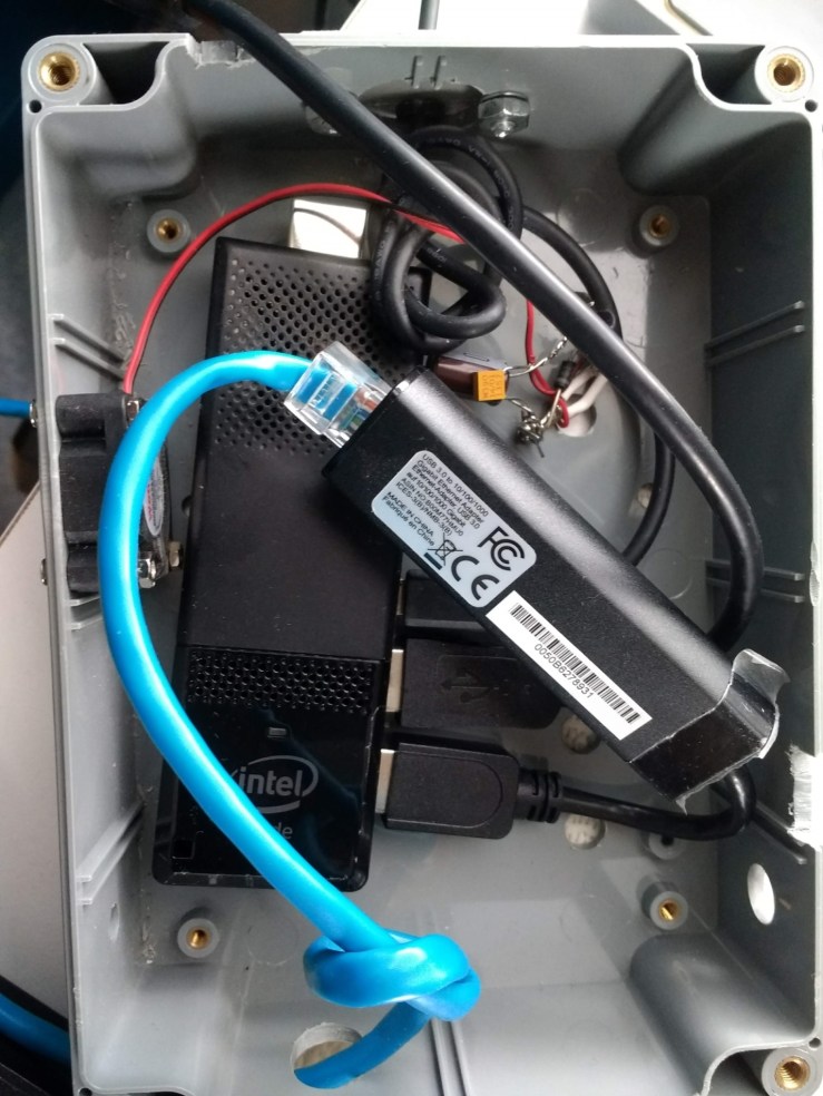
The following figure shows the system mounted on a wall of a fire and security cabinet. The wire coming from the top of the box is a USB port which can be used for the input of a USB camera.

2

The next photo shows the back of the system box. The blue wire is an Ethernet connection which goes to a switch, hub or router. Note the Velcro which is used to mount the system on the fire alarm cabinet.

3

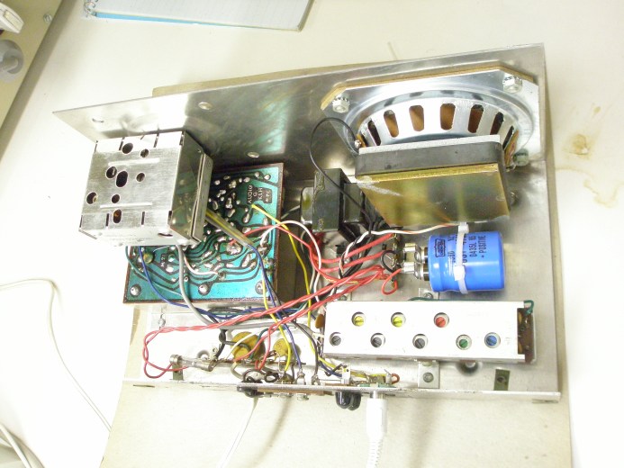
The next photo shows all of the components of the system including the intel Stick, the USB to Ethernet adapter, the Ethernet blue cable, the cooling fan and the filter components for the fan.

4

The next photo shows the system components out of the box.

5

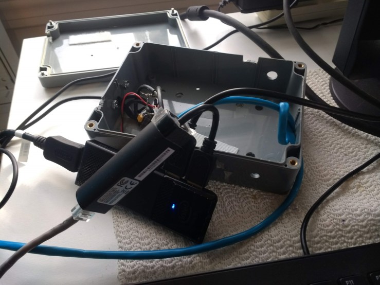
The next photo shows the detail of the fan mount and its filter components.

6

SOFTWARE

Using the free ContaCam software you can configure the system to watch a certain area for movement, record continuously and have a several camera display (like a quad display).

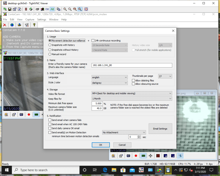
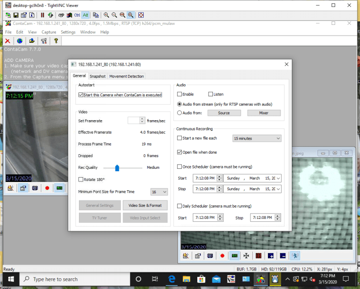
The next illustrations are screen shots of the proper adjustments of ContaCam in my system.

7

8

9

10

11

Insert a large capacity SD card into the Intel Stick. This is your hard drive. Create a file folder for each camera on the SD card.

I set up ContaCam on another system as follows:

12

13

14

Usage: Click Movement detection and 24h continuous recording box.

Name: Enter name of camera

Storage: MP4, Keep files forever, Maximum camera folder size 250GB, Send e-mail on malfunction – enter e-mail address

15

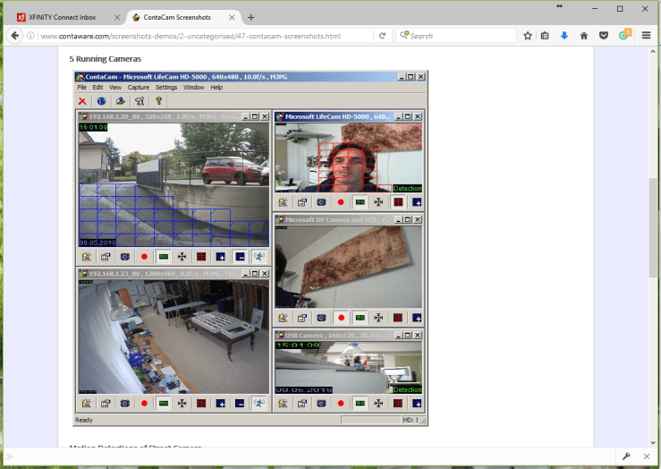
Cameras are set up to display 6 cameras. No zone detection is set up

16

Motion detection not set up on this system

17

Set up snapshots to facilitate reviewing video

18

General:Start with Windows, Tray Icon, Run as Service, Always on top.

The service will automatically run when you start your system.
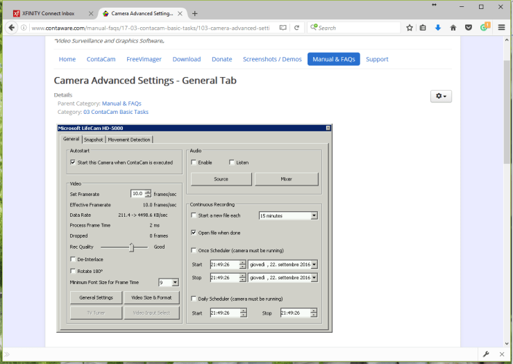
19

Autostart

Framerate: 4frames/sec

Uncheck Open file when done


20

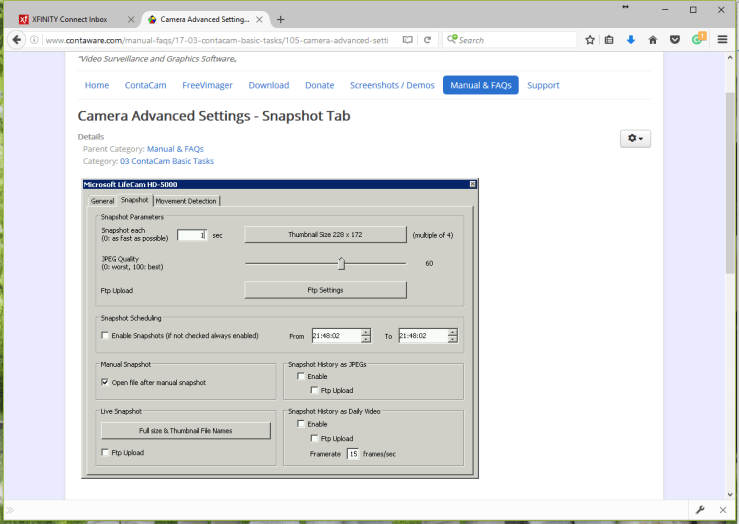
Snapshot every 1 second

You can remotely control this system using another free software application, TightVNC. You can also configure it so you can poke a hole in your router’s firewall in order to view the video anywhere on earth that there is internet.

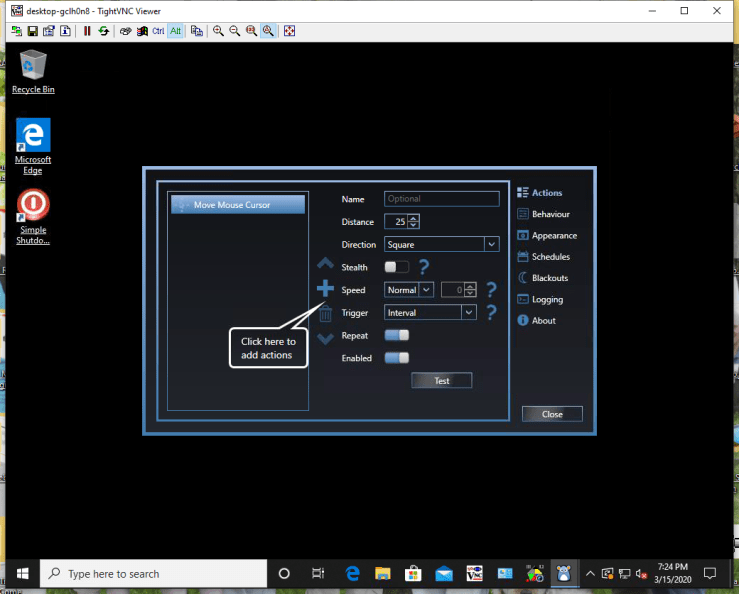
In order to prevent the computer going to sleep you can use Move Mouse that can input artificial mouse movement at a predetermined interval, like every minute. The next illustration shows screen shots of the Move Mouse application.

21

2223

24

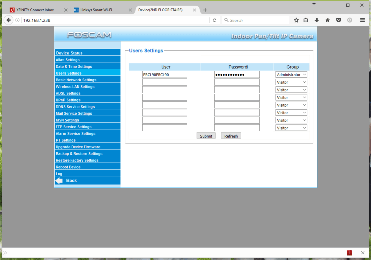
The cameras which I used were inexpensive FOSCAM pan and tilt units. The following shows how to set them up. Find the cameras using the free IP Camera Tool, open a browser and insert the IP of the desired camera in the URL line and then follow the camera setup instructions which follow.

FOSCAM CAMERA SETUP

2526

272829 303132

Click the Server Push mode. This screen shows what the camera is seeing. Click on the device management control pan and tilt with arrows in the circle above.

Enter the name of the camera here on the Alias setting. Chose the right time zone here and click the bottom boxes. Choose 60 minutes when a dropbox appears below the bottom box. The enter the username and passwords.

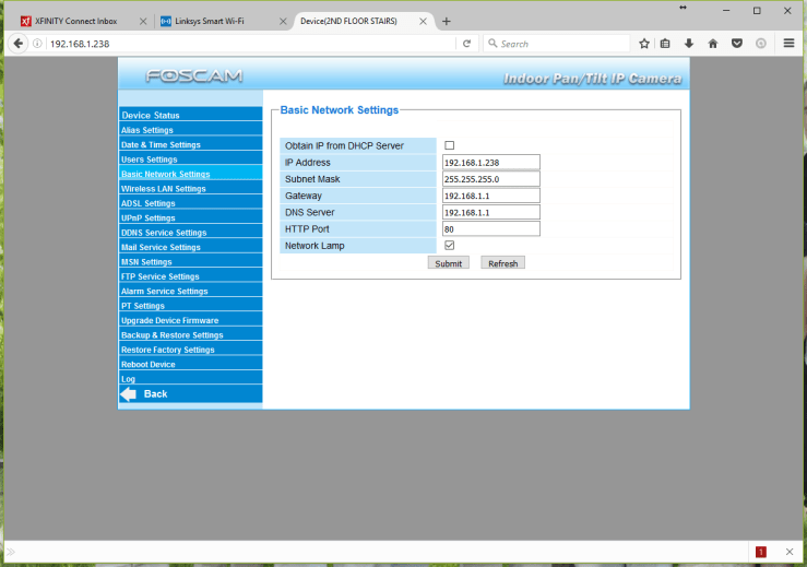
Enter the IP adderess of the camera – I used 192.168.1.X where X identifies the camera. The subnet mask is 255.255.255.0 and the gateway as well as the DNS server is 192.168.1.1. Enter in the port chosen for the camera. The default is 80.

33

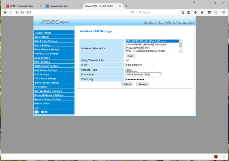
Choose the router from the list. The Share Key should be on the back of it. Make sure that the rest of the boxes are as illustrated.

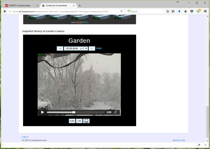
ContaCam has a feature where you can instantly review video from any time. It’s screen looks like this:34

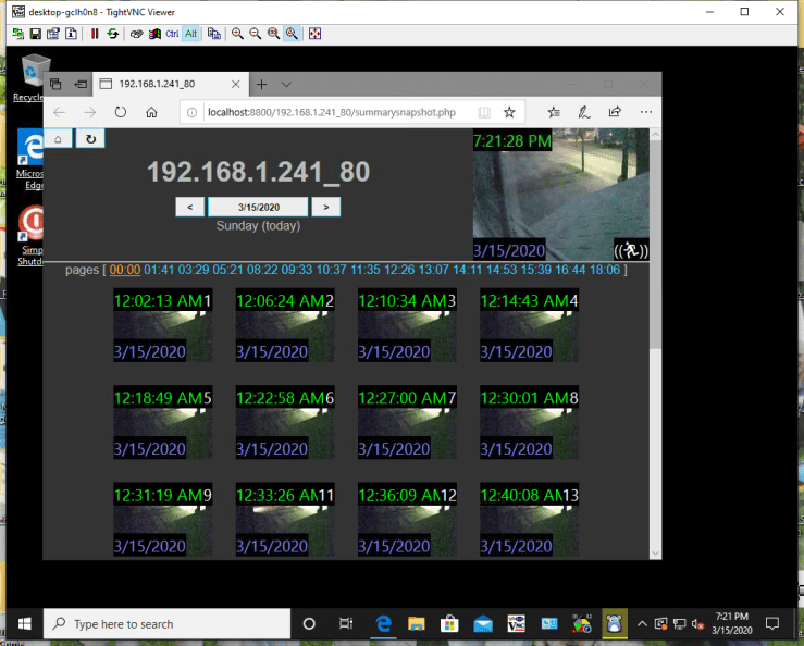
A handy tool to find your camera on your local area network is the IP Camera Tool. Run the free IP Camera Tool and all cameras within range of the wireless LAN system will be listed as below:
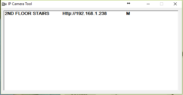
35

PARTS LIST

HARDWARE

  1. Intel Compute Stick with Windows 10 Intel Atom x5 Processor (BOXSTK1AW32SC).
  1. 5VDC Wall Wart included with the Intel Stick
  2. AmazonBasics USB to 10/100/1000 gigabit Ethernet Internet adapter

https://smile.amazon.com/gp/product/B00M77HMU0/ref=ppx_yo_dt_b_asin_title_o02_s00?ie=UTF8&psc=1

  1. 128GB SD card
  1. 6” x 8” x1” plastic electrical box
  2. 1” Wathai 30x30x10mm 30mm 5v brushless dc cooling exhaust fan
  1. 2 – 1n4005 diodes
  2. 1 microfarad capacitor
  3. 10 microfarad capacitor
  4. Foscam Wi-fi F18910W pan and tilt cameras or equivalent

SOFTWARE

  1. Move Mouse
  2. Windows 10
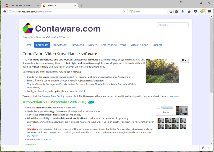
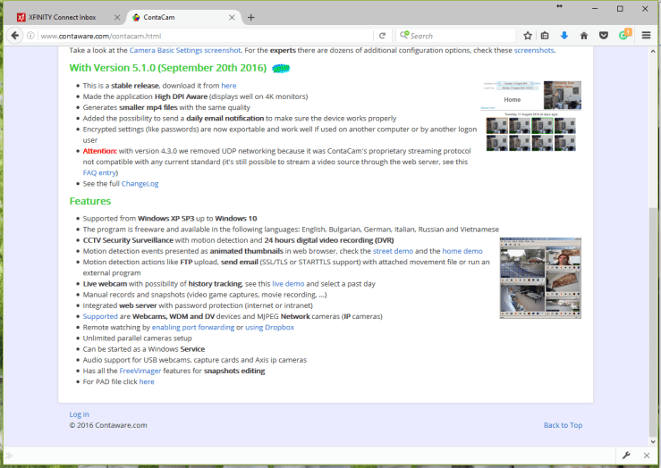
  3. ContaCam- free video software https://www.contaware.com/download.html
  4. TightVNC

– TightVNC remote desktop software-32 bit

https://www.tightvnc.com/download.html

– 6″x8″x1″ plastic case –

(I used a plastic box I has on hand)

– 1″ fan with steering diode and capacitive filter

https://smile.amazon.com/gp/product/B07PDK1MJ2/ref=ppx_yo_dt_b_asin_title_o00_s00?ie=UTF8&psc=1


Equipment Manuals

Library Level Router

http://downloads.linksys.com/downloads/userguide/1224699372213/MAN_EA6900_8220_01617A00_Userguide_EN.pdf

Netgear N300 WiFi Range Extender WN2000RPT

http://www.downloads.netgear.com/files/GDC/WN2000RPT/WN2000RPT_UM_8Dec10.pdf

Foscam FI8910W Wireless Camera

http://foscam.us/downloads/FI8910W%20User%20Manual.pdf


A KLH 21 FM Receiver (2009)

I dug back through the AudioKarma archives to get this gem. The radio is now with my parents. My niece loves turning the knobs to make the radio do ‘funny’ things. If all goes well we’ll be listening to ‘Alice’s Restaurant’ during Thanksgiving dinner this year.

This is a very incomplete write-up, from before I cared to write these things and just wanted to get on with it. If you have any questions, please ask.


I got this at the Westford MA Radio Fair this year. And I paid too much for it, as usual. After a couple hours of use, one of the knobs cracked off; a poor repair job by the former owner failed. So disappointed.

By summer, I got fed up with the polyurethane somebody slathered on. I wanted this radio to be just like the one I remember from my favorite old book store, with a resident cat patrolling the stacks and classical music from this Cambridge-made gem. So, I stripped it back to the veneer. I applied a Walnut Danish Oil to lightly stain back from the slight bleaching of the stripping process, then Tung Oil to finish, polishing with 0000 steel wool, then a couple applications of finishing wax. I’m happy.

klh21a
Nearly complete KLH 21 – waiting to push those fragile knobs on for later

The original and grungy plastic grill cloth had shrunken over the years. I could clean it but a noticeable gap would always be there. It looked ugly. I ripped the cloth off the Masonite front panel, and replaced with an open monks-cloth from JoAnne Fabrics. It was expensive, $10/yd.

klh21d
Application of monks-cloth on KLH 21 front panel board

Of course, you have to accept some things to use the stuff; It ain’t the original cloth; and cloth is a loose term for the original material. The threads in the original was a white PVC-like monofilament, woven in the same fashion of monks cloth, but with the occasional wide noodle-like white thread and yellow thin thread. Perhaps it went: white noodle – yellow – white – white – yellow – white noodle…

Anyway, I accepted the ramifications of this less acoustically transparent fabric material in exchange for the VERY nice look of it. I put down a single thin coating of spray-on contact adhesive (not Super 77, too thick and gummy) to attach. To protect it from being so easily stained and warped, I sprayed it with a clear uv/resistant varnish. I dabbed woodworking glue around the edges of the Masonite panel to reinforce the cut edges; a little glue in the hole edges made cutting them out worry-free.

The cloth I used gives slightly more resistance to airflow than the original PVC cloth, and while I’m not sure how much this will impact speaker frequency response, I cannot say it won’t. It is also all cotton, and if you leave it unprotected and touch it with dirty hands, you’ve now got an essentially permanent stain. (ed. – Three nieces and seven years later, no stains yet…) The overspray of varnish helps to stiffen and set the cloth and help protect the surface.

With all of that said, don’t it look pretty?

Because I’d like to use the radio 24/7 (music for the bird room), I recapped it completely and replaced the rectifier diodes.

In this original write-up, I left out MANY details. Here they are:

I completely left out how annoying working on this was is; KLH equipment always seemed to exchange serviceability for look and size. Look at the PCB, IF strip and tuner section. Each one needed to be removed to get proper access to it. The boxes were soldered shut, and PCBs mounted in the most inconvenient way. The main filter can replacement and the alignment was easy however. This is still nothing compared to how bad restoring the KLH 18 FM tuner is.

The knobs? They were all cracked and nearly falling off. I wonder if the combination of UV exposure, chemical composition of the plastic and the compression clip retention design makes the knob susceptable to this failure mode. Anyway, I went on eBay to buy a parts unit from a similar KLH FM/Turntable unit for the replacement knobs.

I also left out the process of refreshing the rubber on the rubber-coated fabric surround on the speaker with Permatex Black Rubber sealant. I also replaced the foam gasketing along the front and pack panels. Because the case acts like a traditional acoustic suspension enclosure for the single speaker, some degree of air sealing is needed for best effect from the speaker.

klh21b
KLH 21 Out of Case for Alignment
klh21c
Front View of KLH 21 without front cover, re-‘gummed’ speaker

Since those replacement knobs are still so fragile, I held off from pushing them on until I was completely  done working on the radio. Alignment was completed with no issues. I did such a nice job, my girlfriend thought it was way too nice to abandon in the bird room. So, it shall be a gift to my parents for the formal living room.

OLYMPUS DIGITAL CAMERA
All done – ready to play

Would you like see a master’s work on this radio? See Phil Nelson’s KLH 21 here. Enjoy!

An H.H. Scott LK-60 Integrated Amplifier (2009)

I was on a real vintage audiophile kick in the late oughties; I think I owned an example of every style of speaker for a while, and many different amplifiers, preamp, turntables, and a whole bunch of other things. It was fun while it lasted, but interests change. I’ve cut down to a single Harmon Kardon amp, a U-Turn turntable and a good set of Sennheiser headphones. I spend my money now on finding good deals on vintage vinyl.

I wrote up a couple of my restorations through the AudioKarma forums. From time to time, I still get questions about that work. Before that work disappears to the digital sands of time, I am going to move over a couple of the better threads here. Enjoy!

The H.H. Scott LK-60 was an early solid-state integrated amplifer kit based on the H.H. Scott 260. I got these for free, off my local Freecycle. Not one, but two of these beauties, one with a tone circuit issue, the other an incomplete parts unit. Both were in wood cases, nice looking front panels and knobs, and the complete assembly manuals with all the paperwork (included receipts and warranty cards). All this was given away by the original builder.

The photos, as blurry as they are, cheat a little. I’ve cleaned the front panel and knobs, and refinished the case. But since I’ve yet to spend money on stuff for it, it’s still free…right?

The LK-60 is essentially the kit form of the H.H. Scott 260 – they appear to be the same, right down to the boards used. As a kit the work is a bit easier than a Heathkit; these boards were pressembled and tested – “”All”” the kit-builder had to do was solder the wires and chassis components, and do a bunch of mechanical assembly. They had to be adept at wielding a soldering iron since all the wiring was PVC which melts and shinks with any application of heat.

I start my restorations with a cleaning up of the outside. If I don’t see that it will look pretty enough to have in my living room, why bother doing anything else?  The front panel took some babying – the panel lettering is fragile and only silkscreened on – so no hard scrubbing or you’ll lose them. The thin finish on the veneer wood case (I got two in this deal) needed some attention. I cleaned it up with Minwax Antique Furniture Refinisher and then applied several layers of Walnut Danish Oil with light sandings in between. The aluminum grille had a yellowed layer of laquer that I quickly removed with hot water and degreaser.

(ed.: the knobs took the most attention. the brass caps were dull and were barely hanging on to the plastic. I’ll write up the process on how I recovered those another time)

I like my electronic restoration to look like it belongs, especially when somebody can see inside. There are a large number of electrolytic caps to replace in this amplifier, and radials will not do. I could not find an axial capacitor series that would fit all of the values without selecting far larger voltage rating, and while the old caps were big, they weren’t that big. I bucked the conventional wisdom of using the best Panasonic or Nichicon radials I could find, and selected the axial Sprague TVA Atom series.

Why, Dave, why? I hear the scoffing. ‘They have substandard audio performance’ (whatever that means). Lower lifetime ratings. They are not Japanese. OK, here is my logic.

One: Atoms are still better than the original capacitors from back in the early 60’s. We have the benefit of decades of capacitor design and process control and automation, resulting in a far more consistent and higher performance part.

Two: The theory of better caps making an entire audio device better sounding smacks of magical belief. If I put in capacitors of similar design into this amplifier, I ‘should’ get similar performance to that originally designed and approved by the engineers who designed this.Which seemed good enough for this to be considered a fairly decent amplifier back then.

Three: Axials are going to look WAY nicer on these PCBs, and will exactly match the original component values. Making that decision made the work easy, since they fit very nicely and you can get old-fashioned values (5uF, 50uF, those wonderful old round numbers).

I will tell you that with capacitors, most of my time was spent finding the perfect output capacitor. If you are concerned about the quality of the part affecting performance, that’s the first part to consider. I spent a lot of time finding the perfect cap with for screw terminal and the same outer diameter, so they could drop right in. Large crimp terminals made the reattachment easy.

My restoration process:

Remove bottom cover, preamp circuit cover, front panel, knobs, panel meter, fuses

Get your iron hot, and then let’s remove each of the circuit boards.

QUICKLY heat the joint between the wire and PCB terminal point, and pull up on the wire(s). You want to do this quick since the wire insulation is PVC and will melt/shrink when hot. Keep the wire in about the same area of the chassis, this helps later. Once you have freed a PCB of all the wires connected to it, remove the four screws (two screws for the preamp board) and lift the board away. Repeat five more times; don’t worry, the boards are exactly the same between the right and left sides.

One by one, clip away the old capacitors. You may take notes of position and orientation; this is already in the manual on the back of the schematic page. Working fast and deliberately, use the wick to remove the solder and remaining leads. Clear as much as the solder as you can from the terminal points without heating the board too much – this is where you want good soldering skills – the better you clean the points the easier it is to reassemble, but if you heat the joint too long you will delaminate the attached trace from the board.

If your board has socketed transistors, remove them but take careful note of their position on the board; on the driver board the same transistors are used but they seem to have sorted them in some way. It’d be best to try and maintain the positions of those parts. Now pour alcohol into a bowl/basin, and using a small paintbrush, delicately scrub the top and bottom sides with the alcohol (about 30-45 seconds) over a sink. Then dip the board in the alcohol for a final rinse for 10 seconds, then holding the board firmly, flick it dry. I have sometimes used a water rinse, but I usually follow it with a bake in a warming oven. This absurd amount of work removed dust, flux residue, oils, and will leave you with a clean good-as-new board. If you are doing the driver board with the two pots, use compressed air (or the can-type ‘duster’) to blow out the alcohol/water, then follow with Deoxit/FaderLube to replace the lost lubricants.

At this point I took the time to measure all of the resistors on the boards and chassis. The general rule is that you should never see a resistance HIGHER then the nominal+tolerance of the resistor, sometimes within, and sometimes lower. As you have removed/disconnected alot of stuff, you are going to find that most resistances are within their 10% tolerance. For the low ones, go back and desolder, lift one side out of the board. You should be able to measure the resistance without the influence of other parts once you do this. I found that there is a minor resistance change on the preamp boards not documented in the schematic. If somebody is interested, I’ll find it. Replace any out-of-tolerance resistors with 1/2W carbon-film types or carbon comp if you can get them new (no NOS).

Now to replace the capacitors. Estimate the points to bend, and bend with your needle nose pliers. I can tell you now that none of the capacitors get bent right at the body, there will be the need for at least a little lead on each end. Insert, bend the leads long the path of the PCB trace, and cut with your diagonal pliers such that you have about 1/8″ laying on the trace leading to the pad. Solder. Over and over again! Once you’ve finished, inspect your work, checking for joints you forgot to solder, incorrect polarization or component values, or any other damage. Repair as required.

You might think – hey, how are you going to wire all that back up? So many connections! As this was a kit using prebuilt boards, all the instruction manual describes as how/which color wire goes where. My manual is my notes!

One by one, reinstall each board. Clip a short section of heat shrink and slip over the wires. Bend the end into a squareish loop, and press into the slot of each board terminal. Along the way think about how the wires are sitting on the chassis, and rearrange the wires for nice clean and orderly runs. Don’t solder yet, until you know that no more wires are going into the slot – Scott broke up the wiring for all but the preamp board into multiple sections. Once you have all the wires in place for a board, recheck the drawings, then solder. Slip down the heatshrink (because the PVC shrinks, don’t it?) and use a heat gun to complete the operation.

Do a final check of the wiring, looking for forgotten connections, wrong connections, burned insulation, etc. Repair.

Remember the mechanical/electrical parts you removed? Put them back in, in the same order/location you took them out of. At this time, if you’d like to replace the old clear thermal compound with white thermal compound, now is a good time. Take care to remember the orientation of the QA-10 transistors in the heatsink. If you want to do the same for the 2N3055, It only takes two screws on the underside of the chassis to loosen each heatsink block for access and two more on each transistor.

Put the front panel, meter, knobs back on. Good tools prevents damage.

Everything back together? Again, go over the whole thing, comparing it to manual photos and other photos…then do the Initial Test as described in the manual. This is a neat kit – they have an ‘INITIAL TEST’ position to allow you to determine if you dead-shorting something without destroying the amp. It passed in the first go.

If that goes well, do the balance and bias procedure, and if that goes well, stick in some headphones, connect an iPod or hat have you to the extra input, and try things out. Run it for a long duration at low power, shake/poke/turn to try things out. I had an issue with weak audio on one side – but with a little debugging, the problem is resolved, and glorious, rich sound is coming from the KLH 24s I’ve hooked up to them. I ran the detailed test procedure in the manual, buttoned it up and I’m done! Another classic restored.

I liked this restoration so much, I got the matching LT-112B FM Tuner and restored that. They look nice together, eh?

OLYMPUS DIGITAL CAMERA
The H.H. Scott Kit Pair – LK-60 Integrated Amplifier and LT-112B FM Tuner

Like many of my projects, I lose interest in actually using the thing after rebuilding it. That is always where I found the fun. So, I tried selling it on Craigslist for what I thought it was worth; nobody agreed with my valuation. So, onto eBay it went. I sold it to a fellow in North Carolina, who wrote me this after receiving it:

THE MOST BEAUTIFUL RESTORATION I HAVE EVER SEEN, extremely well packed…Hi David. I am enjoying the Scott amp. It sounds great..you really did a good job with it. In light of that, I feel you didn’t get as much through the auction as you should have. If you will give me your address I will send you a check for 135.00. I feel this is fair. I don’t want to go through ebay or paypal, so let me send it to you.

It was incredibly rewarding to get this kind of praise, and I’m glad the amplifier is going to an owner that will appreciate it.


Parts List

All Parts from Mouser Electronics

Chassis Components (first section caps, second is optional stuff)

(2) 539-CGS222075R2C 2200uF 75V Screw Terminal Capacitor
(1) 75-36DY102F100AN2A 1000uF 100V Screw Terminal Capacitor
(1) 594-2222-021-19102 1000uF 100V Axial Capacitor
(1) 75-TVA1312 250uF 50V TVA Atom Axial Capacitor

(2) 844-1N1206A 600V 12A stud-mount rectifier
(1) 863-1N5361BG 27V 5W Zener Diode
(1) 606-CM1819 #1819 Lamp
(2) 581-5OQ472KOHAM 0.0047 uF ceramic capacitor (one extra inc.)
(1) 30BJ500-39K 39KOhm 1/2W resistor

Ring Lugs from personal stock

Driver Boards (both inc.)

(2) 75-TVA1414 50uF 150V axial
(4) 75-TVA1161 250uF 16V axial
(2) 75-TVA1206 50uF 25V axial
(2) 75-TVA1306 25uF 50V axial

Tone Boards (both inc.)

(2) 75-TVA1160 100uF 16V axial
(4) 75-TVA1306 25uF 50V axial
(4) 75-TVA1204 10uF 25V axial
(2) 75-TVA1301 2uF 50V axial

Preamp Boards (both inc.)

(2) 75-TVA1161 250uF 16V axial
(4) 75-TVA1204 10uF 25V axial
(2) 75-TVA1206 50uF 25V axial
(2) 75-TVA1303 5uF 50V axial
(2) 75-TVA1301 2uF 50V axial

An Autronic Single Paddle Morse Key (2016-17)

I have been solely a single paddle key guy, and was taken with the look of the Autronic after looking to upgrade from my current key. But with the positive reviews, they now can go for quite a bit. I searched around – and found this small heritage vegetable seed company selling one of these keys, with the nice looking conical lock nuts. BUT – it was missing one of the contact posts entirely, as well as both of the springs. Eh, I think I can find somebody to help.

Here is what we are starting with.

But why is a seed company selling a key? The seller said this:

The history of the key is it was my Grandfather’s.  He served in the Navy many years ago.  He passed away in 1982.  My parents inherited the estate and this was part of all the stuff.  I just recently was given a bunch of items from moving my parents to a new location and the items I didn’t have a need for or sentimental attachment to , I put online.  So the missing parts, sorry to say, are long gone after all these years and moves.  I sure with your skills you will get back in top notch shape!

The package finally arrived, and after clearing off dinner from the table, took my new key to pieces and looked at what we had to work with.

We are missing parts these parts: contact post, contact screw, 2x plastic washers, 2x springs. Everything else looks nice; the plastic paddle finger pieces are in good shape, as is the paint on the cast aluminum base. Even the rubber feet are still sticky enough to keep from sliding around my stainless steel table. The bones here are good but some work is needed.

My original idea was to buy some similar parts and adapt them as needed. I would have the plastic washers 3D printed. While looking for those parts, I found the website of 2BRadioParts.com (Donnie WA9TGT). Since his original work supporting the Drake radios, he has moved onto the fabrication of MANY replacement parts for bugs and keys, including replacement finger pieces for the Autronic. So, I wrote him an email.

To my surprise, Donnie offered to perform a restoration. He had a similar Autronic to compare to.

His plan was to:

1. Fabricate TWO new contact posts and conical lock nut from 6061 aluminum
2. Fabricate a new pair of plastic washers. The two original ones would be placed ‘top side’ and these new ones below.
3. Convert a stainless steel screw into a replacement contact screw
4. Find similar springs and modify into replacements of the correct length and end tapers, modelled from his own key

Surprisingly, he was already mostly done in just two days!

duztt2h
Autronic Key Restoration In Progress

My key on the left, his on the right. You can see the conical lock nut in progress in the center. The springs and contact posts are new. In a couple more days, it is all done and ready to ship.

The replacement contact screw is machined from a 6-40 stainless screw, with the same flat notch that all of the other screws.

iz6kdlt
Replacement Contact Screw

And here it is, all done…

v7ueh0mjovtejk

What do the 2 adjusters that stick out from AUTRONIC labelled part do? They do different things. Its an interesting mechanism, using a center paddle arm and asymmetric yoke to produce the required self-centering without limiting the adjustability for dit and dah motions. Besides what you can see in the image, the top left side adjuster is a centering adjustment and the top right side is the dit spring force.

The patent and drawing may help: https://www.google.com/patents/US3098898

Here is a quick video of the key’s unique adjustment mechanism.

What remains to be done is to add a cable that will match how nice this looks. What would be really nice is some super-flexible stuff that will lay flat on the desk and matches the grey of the cast base. Maybe something like EcoFlex, or a fabric braided cable used for audio. I have some digging around to do. So, more to come.

Update Sept. 2017: I found a braided-jacket 1/8″ TRS audio cable from my local electronics store, with a grey tone that matches the wrinkle paint.

completed_autronic_key


This was my first project working as ‘project manager’ – I did some stuff but when it comes to the details, finding the right person with the skills, experience and tooling made all the difference.  This was made possible by the fantastic work of WA9TGT. Donnie is the man! At least from his website, restoration isn’t main business – he usually make up parts and replacement finger pieces for many keys – but when he does it, it is done VERY well. Be sure to check him out.


Thanks to Charlie WA2ONH, here are some related links:

Autronic Paddle

Later Autronic Ad for “Perfect Code”

N2FQ Autronic Cleaning Video